How Do I Comply With Concrete and RWFD Retrofit Ordinances?

Most retrofit ordinances follow a similar formula and typically include the steps outlined below. These will vary by jurisdiction, including special requirements for San Francisco and Los Angeles.
- Notification: Prior to implementing an ordinance, the city, its consultants, or engineering volunteers typically conduct a survey to understand the number of buildings potentially possessing the risk(s) requiring mitigation and compile a list of addresses and owners. The owners of these buildings are then notified that their building may potentially be in the class containing these hazardous conditions. If the building owner is not notified but knows that their building is the type that should receive notification, they should comply as if they were notified.
- Screening: Following notification, the building owner must hire a qualified professional (structural or civil engineer, sometimes architect) to determine whether their building falls within the ordinance’s scope. This screening often requires filling out a form that includes a checklist of hazards and deficiencies.
- Evaluation: If the building does fall within the scope of the ordinance, the structural engineer then performs an engineering evaluation to determine the scope of the problem. This evaluation can be simple or sophisticated, depending on the building and scope of the ordinance. More sophisticated analyses are more time-consuming and expensive but generally provide more accurate results (especially for irregular buildings) and frequently show that more existing structural elements are satisfactory. More sophisticated analyses often save money overall by reducing the scope of the retrofit and consequently reducing construction costs. For most buildings, construction costs are expected to far exceed those of the evaluation and retrofit design by an engineer.
- Retrofit design: After the engineering evaluation, the structural engineer will use that information to design a retrofit (or strengthening) scheme to mitigate problem areas. Documents that typically include drawings and calculations are produced and submitted to the building department for review and acceptance. The permit submission requires the estimated construction cost, which is generally provided by the contractor that the owner chooses.
- Retrofit construction: After the city accepts the retrofit documents, the owner provides drawings to a contractor to confirm pricing and scheduling. Once the owner accepts the bid, the construction process begins. During the construction process, the structural engineer will need to provide construction services, and the owner will need to hire a testing lab or special inspector to test material strengths and inspect the work.
How Are NDC Buildings Evaluated?
Evaluating non-ductile concrete (NDC) buildings generally falls under two main categories:
Building Code-Based Evaluation
In this approach, the existing building is evaluated using the current California Existing Building Code (CEBC). Generally, retrofits of existing buildings use a reduced level of force (typically 75%) compared to the full California Building Code (CBC) force. However, one must understand that the CBC is primarily written for the design of new buildings. Hence, trying to use it to evaluate a building that lacks modern seismic detailing poses a challenge and is not recommended.
The normal (and usually conservative) way this is tackled is by giving less credit to the building’s existing lateral system than it has. In engineering parlance, this is done by classifying the building’s existing shear walls or moment frames as ordinary (that have the lowest seismic performance) rather than something better, or in some cases, ignoring them altogether. This forces the engineer to add newer and more modern retrofit elements to make up for the deficit in lateral strength. A building code-based evaluation is most appropriate for an existing building when a totally new lateral load system is provided.
Another shortcoming of the code-based, prescriptive approach is that there is less confidence in the building’s performance. For example, if the owner wants to have an immediately occupiable building following a specified moderate earthquake, the confidence is not high that the code approach will deliver a building that can meet that goal.
Performance-Based Design Evaluation
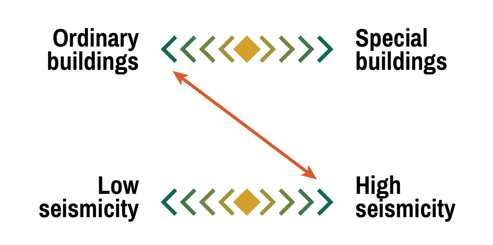
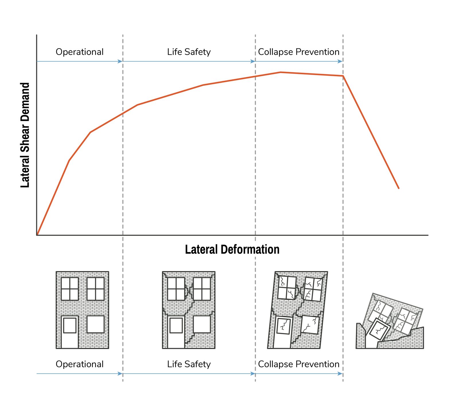
Performance-based design (PBD) has gained tremendous popularity over the last twenty years. Using this method, the engineer can evaluate any type of building for any level of earthquake. For example, an oft-used performance target for existing buildings is the Basic Safety Objective for Existing Buildings (BSOE) in the national standard ASCE 41 – Seismic Evaluation and Retrofit of Existing Buildings. The BSOE is intended to achieve life safety performance for a strong earthquake (an earthquake with a 250-year return period) and collapse prevention performance for a severe earthquake (1,000-year return period). See the figure below for a graphical representation of the performance limit states for buildings.
Using PBD, engineers are not handicapped in using only lateral elements, such as concrete walls and frames that meet certain detailing requirements of the building code. As a result, every wall and every frame in the building participates in resisting the proportion of lateral loads that they attract in a seismic event. The outcome is often a more competitive and cost-effective retrofit, where the real savings are achieved in terms of construction time and materials.
Another advantage of PBD is the ability of engineers to use advanced analysis and laboratory experiment results that have not yet been incorporated into the building codes. Pushing lateral force elements further and allowing and accounting for damage results in a more efficient design that is unencumbered by the limitations and restrictions of the design approach embodied in the CBC.
An often-unheralded success that can be achieved using PBD and advanced analysis is the significant reduction in the extent of foundation retrofit work. Building code-based evaluation typically relies on holding the footings for tall or narrow walls down with vertical hold-down elements, such as tension piles or micropiles. Inserting such foundation elements in the existing basement of a multistory building can be expensive and challenging. On the contrary, using advanced analyses, engineers can allow the foundation to rock and eliminate the need for vertical hold-down devices, as was done by SGH in the Lane Building project.
How Are NDC Buildings Retrofitted?
Retrofitting an NDC building can be done in many ways, depending on the building’s specific deficiencies. If there are major deficiencies in the strength of the seismic-force-resisting system, such as walls or frames, which may often be the case, a new lateral-load system may need to be constructed to supplement the existing system. This may involve adding new concrete walls, infilling existing wall openings, or adding steel-braced frames. Alternatively, the existing concrete walls can be enhanced by adding reinforced shotcrete to existing walls, making them thicker and stronger. These new systems typically result in the need for foundation work. Similarly, if there are geometric irregularities, new elements may be provided, or existing elements enhanced to address these irregularities.
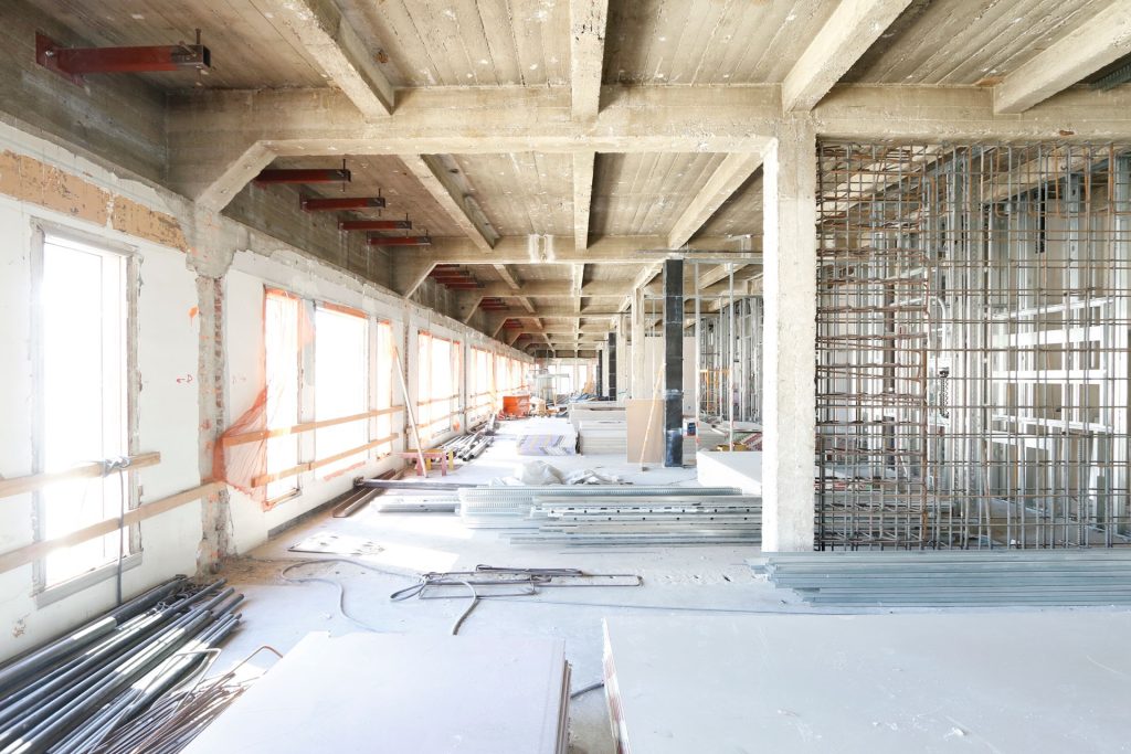
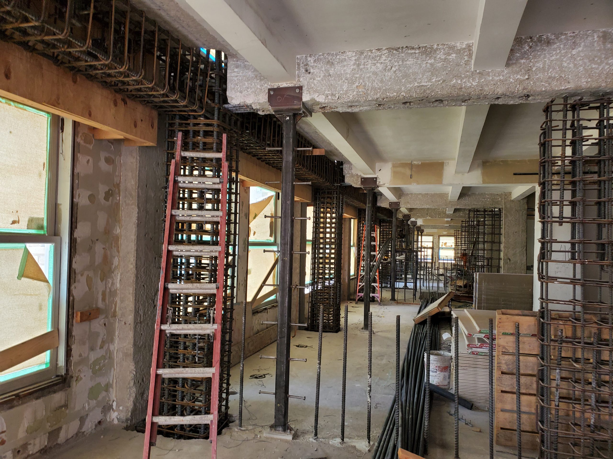
New wall reinforcement visible between existing columns.
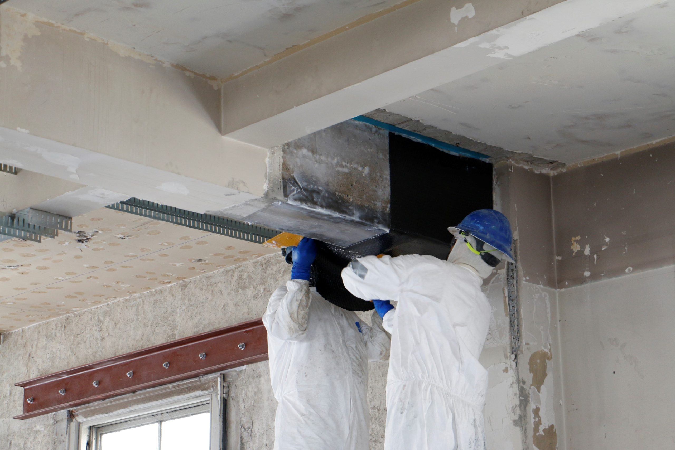
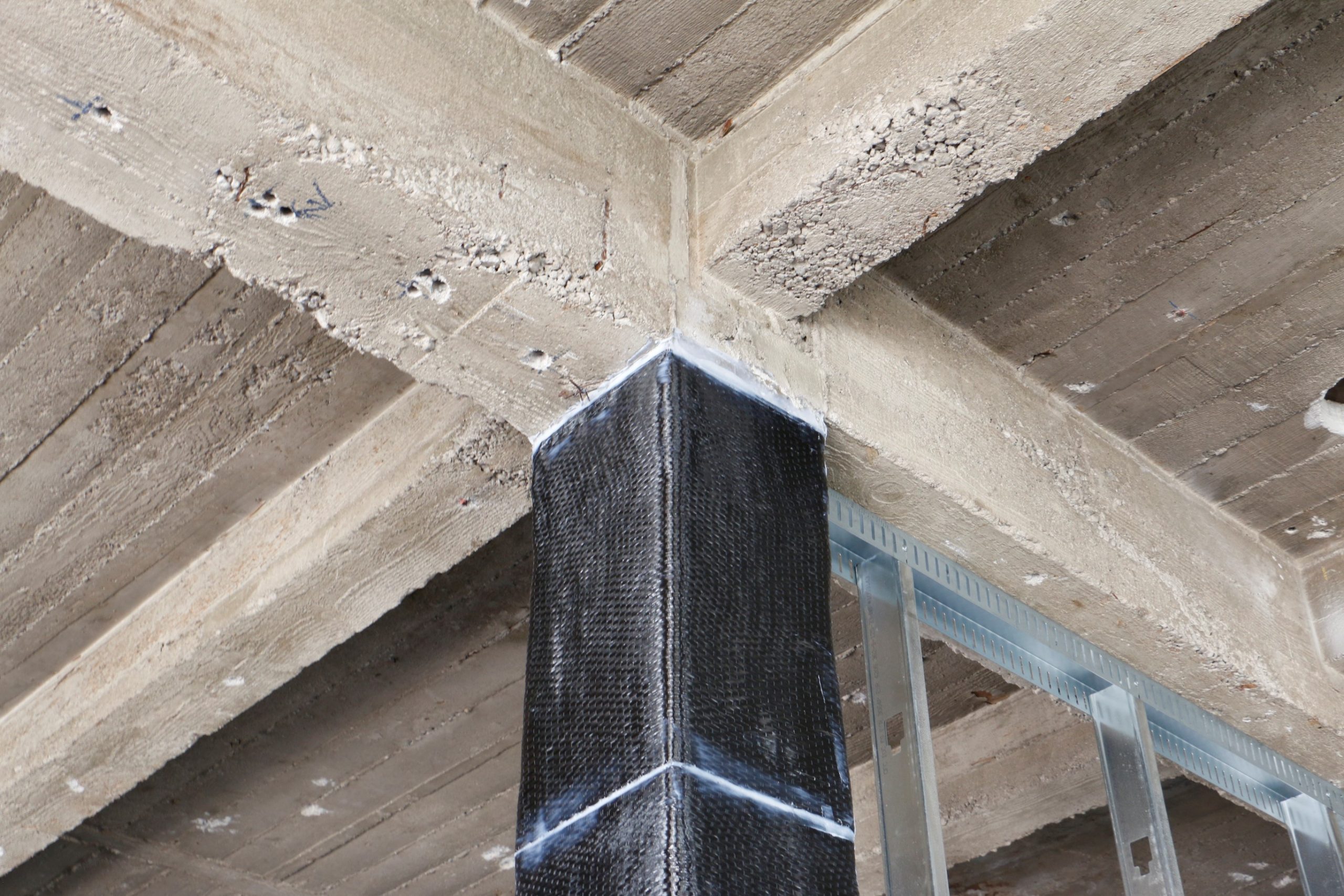
The lack of well-detailed and spaced steel hoops (referred to as ties) near the top and bottom of concrete columns at each floor is a common deficiency in older concrete buildings. Strengthening could be achieved by increasing the size of the existing beams and columns by casting new reinforced concrete around these elements. However, a relatively simple fix for this is to wrap the columns in fiber-reinforced polymer (FRP), a material often used in boat and vehicle construction. Carbon composites have a high strength-to-weight (as well as volume) ratio and save valuable rental space that would otherwise be lost to concrete encapsulation. In the Lane project, we used carbon composite fibers to confine the concrete and strengthen the existing beams and columns.
Beams aligned with shear walls may require strengthening to serve as collectors (beams that collect seismic loads from elsewhere in the building and transfer them to a shear wall). This can be done by increasing the collector sizes by encasing them in reinforced concrete and providing extra capacity with steel rods at columns or wrapping them in FRP. Roof and floor diaphragms may require strengthening locally at openings and near shear walls. Strengthening of collectors and diaphragms can be achieved by applying strips of FRP on top of the concrete along the edges of openings or near shear walls. We used such FRP in the Fickett Towers project to act as collectors and in the San Francisco State (J. Paul Leonard) Library project to improve diaphragm capacity.
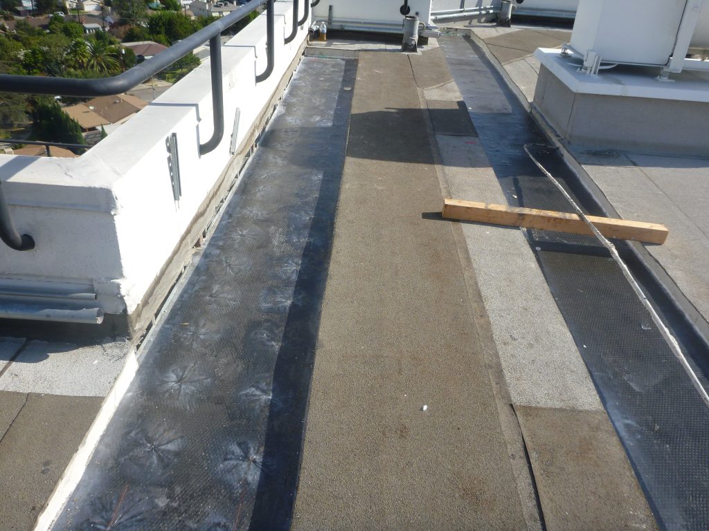
Using FRP as collectors on existing floors.
New or strengthened lateral systems often require new or upgraded foundations. Foundation work can be intrusive and expensive, so in some cases it is worth performing advanced analysis to explore ways to minimize or avoid this work, for example, by allowing controlled rocking of foundations or by limiting forces through yielding or damage in the superstructure. We used this approach to limit foundation strengthening at the Lane Building and J. Paul Leonard Library projects.
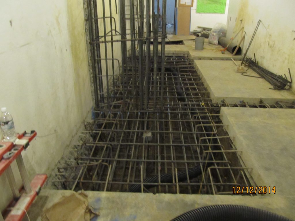
New foundation work being prepared for future column.
If the building has unreinforced masonry walls or infill, they can sometimes be removed and replaced with concrete walls. If they are not removed, some mitigation of their associated risk of failing and falling is required, such as using FRP, steel stud strong backs, or wire mesh to catch falling masonry.
Hollow clay tile walls stabilized with strongbacks.
How Are RWFD Buildings Evaluated?
For compliance with ordinances, rigid wall flexible diaphragm (RWFD) buildings are usually evaluated using Appendix Chapter A2 of the California Existing Building Code (CEBC). This is a building code approach specifically developed for RWFD buildings using reduced forces (75% of current building code forces). The scope of the evaluation is limited to those items observed to result in frequent damage in past earthquakes in California. Consequently, performance in a major earthquake may be substantially inferior to the performance of a new building designed to the current building code.
Based on the damage observed in past earthquakes, the scope of the evaluation using Appendix A2 is limited to:
- Wall anchor systems.
- Collectors and collector connections.
For simplicity, the following discussion assumes wood roof framing and diaphragms, which are common in older RWFD construction. A similar discussion applies to metal roofs. The evaluation is more straightforward if original design drawings and any modification drawings are available. In the absence of drawings, it may be necessary to remove portions of the roofing to verify the presence and type of wall anchors and plywood nail pattern and to investigate other building details using both nondestructive and destructive testing.
The wall anchor system is typically the weakest link in older RWFD buildings. Roofs can separate from the walls and, in some cases, collapse in moderate-to-strong shaking. The wall anchor system for an RWFD building includes:
- Wall anchors (steel hardware and anchor rods connecting the walls to the roof framing, referred to as struts).
- Struts (framing supported by and perpendicular to the walls, the struts also typically support gravity loads).
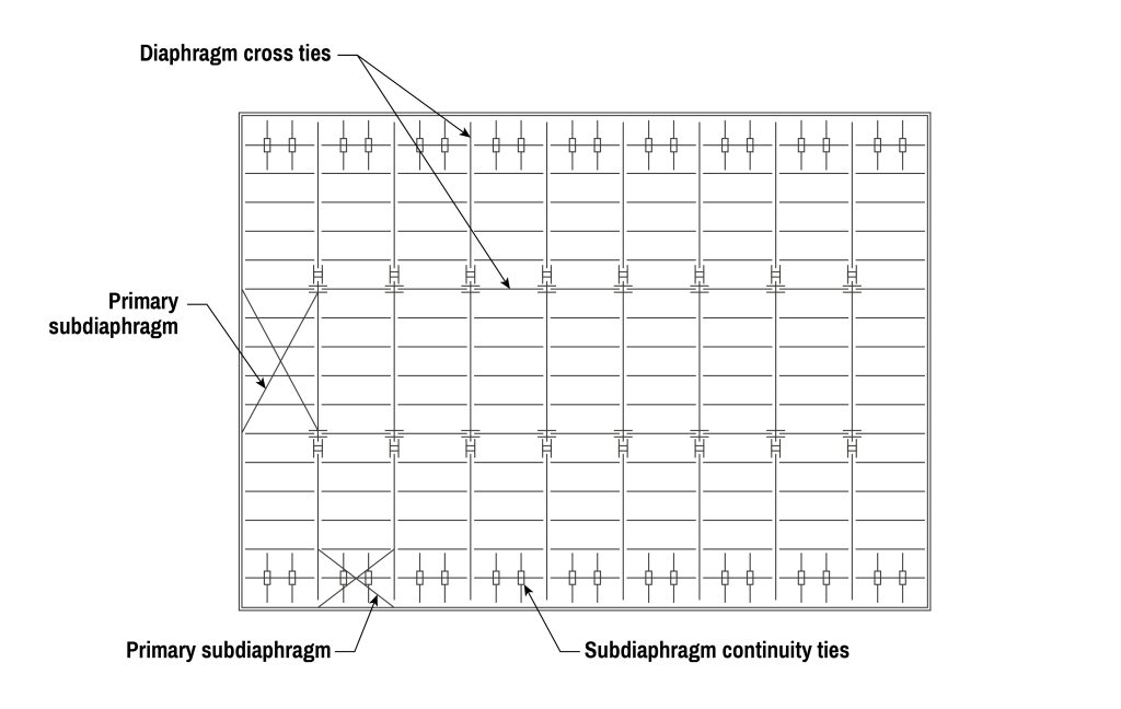
- Subdiaphragms (a portion of the roof diaphragm adjacent to the wall to which the struts transfer wall anchor forces).
- Continuity ties (steel hardware connecting roof framing members together).
- Continuous ties (roof framing members connected together at their ends by continuity ties to transfer wall anchor forces across the roof diaphragm).
Thus, the wall anchor system extends throughout the whole roof of a RWFD building. Quality control for installation of wall anchors was typically poor in older buildings, so as part of the evaluation, the engineer should perform a visual survey (often with a ladder or lift) to verify their apparent adequacy if they will be relied upon as part of the retrofit. Pull tests on anchor bolts in concrete or masonry walls may be appropriate.
Wall anchorage system.
Wall anchor design forces first appeared in building codes in the 1970s and have increased significantly through subsequent research and post-earthquake findings. By 1997, code-required forces were several times higher than the original values. Current provisions also impose minimum requirements on strut sizes and subdiaphragm dimensions that did not exist in earlier codes. The stiffening effect of pilasters (concrete columns integrated into walls to support beams) must also be considered.
In practice, evaluations of wall anchor systems in older buildings typically reveal substantial deficiencies. These systems usually require supplemental wall anchors, or in cases where the existing anchors contribute little, completely new wall anchors that can resist the entire design loads. Once new anchors are needed, the incremental cost of designing them for the current code-level forces as opposed to the reduced forces in the ordinance is relatively small. Owners may consider this investment worthwhile for the improved earthquake performance it provides.
Buildings with irregular floor plans, such as L-shaped or U-shaped layouts, are more vulnerable to earthquake damage. These shapes can cause stress points in the roof system and, in the worst cases, contribute to collapse. To manage these forces, roof beams (called “collectors”) are needed to tie the roof and walls together, so the building moves as a unit during shaking. Older buildings often lack strong enough collectors or connections between collectors and walls. When these connections exist, they are sometimes poorly detailed, crowded with reinforcing steel, or built with limited quality control. This is especially true at corners where forces need to be transferred in more than one direction.
Although collector connections only occur in a few spots within a building, they are often among the most complex and critical elements to evaluate and retrofit. In some cases, small areas of demolition may be needed to see how the original connections were built, or new connections capable of resisting the entire design load installed.
There are other cases in buildings where collector-related issues exist besides reentrant corners. Architectural features such as fin walls (short walls perpendicular to the exterior walls) should be addressed. Typically, these fin walls were not considered as shear walls, and no collector connections were provided. This can result in localized damage and perhaps local collapse. Sometimes supplemental gravity supports are provided adjacent to fin walls to support any framing damaged in an earthquake.
Partial mezzanines in RWFD buildings have a history of collapse and wall panel damage during earthquakes. They are often overlooked in design, and later modifications or additions may further reduce their lateral capacity. Mezzanines are usually supported on columns with enclosed stud walls. Ideally, they should be isolated from the main building and provided with independent shear walls or braces. When attached to perimeter concrete or masonry walls, both the walls and mezzanine must be designed for seismic loads and wall anchor forces. In practice, wall anchor demands are the most common issue, but mezzanines lacking a sufficient lateral system can also overstress walls or fail at their wall connections. These evaluations can usually be performed without a full-building computer model.
Although the mandatory evaluation is typically limited to the above three items, other building deficiencies may exist. We recommend that the engineer identify any concerns and let the owner decide whether they should be addressed in the retrofit. Two common areas worth reviewing are the roof diaphragm and the concrete or masonry walls.
For the roof diaphragm, strength depends on the thickness of the plywood and how closely it was nailed to the roof framing (for a metal deck roof, it depends on the metal deck gage and the welds used to connect adjacent sheets and connect the sheets to the framing). Nails are often spaced closer at the building perimeter, where earthquake forces are higher. Without drawings, the nail size and spacing can only be confirmed by removing the roofing in multiple areas.
Concrete or masonry shear walls are usually adequate in RWFD buildings unless large openings leave only narrow wall segments called piers. If the walls appear questionable, a more detailed evaluation may be appropriate, since the original detailing often does not meet today’s standards.
How Are RWFD Buildings Retrofitted?
Retrofitting RWFD buildings is relatively inexpensive when compared with other structures. Many times, retrofits can be achieved without moving all the tenants out of the building. In warehouses, off-working-hour work can sometimes be completed without interruption to operations. The primary deficiency for RWFD buildings is the wall anchor system. Other deficiencies, such as inadequate collectors and collector connections, are common. Additionally, while RWFD structures do not fall under the NDC classification, many older tilt-up buildings share similar vulnerabilities, especially the lack of ductile detailing in wall piers. Owners and stakeholders of older RWFD buildings in San Francisco should closely monitor the future mandatory ordinance’s final language to determine potential impacts and prepare for evaluation and retrofit requirements.
Typical retrofits may include:
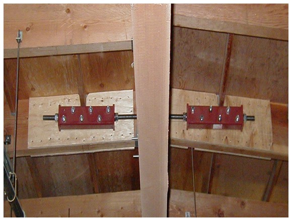
- Adding or upgrading wall-to-roof (diaphragm) anchors to prevent the walls from separating from the roof. Some existing wall anchors are adequate to be used in combination with new wall anchors, whereas others, such as twisted straps, are not. Walls with pilasters will need larger wall anchors at the pilasters. Wall anchors can be provided above or below the roof, depending on which is less disruptive or expensive. For buildings where exterior appearance is not critical, through bolts with exterior bearing plates can be used. If such plates are objectionable, adhesive anchors can be installed and tested.
Wall anchorage installed on existing purlins.
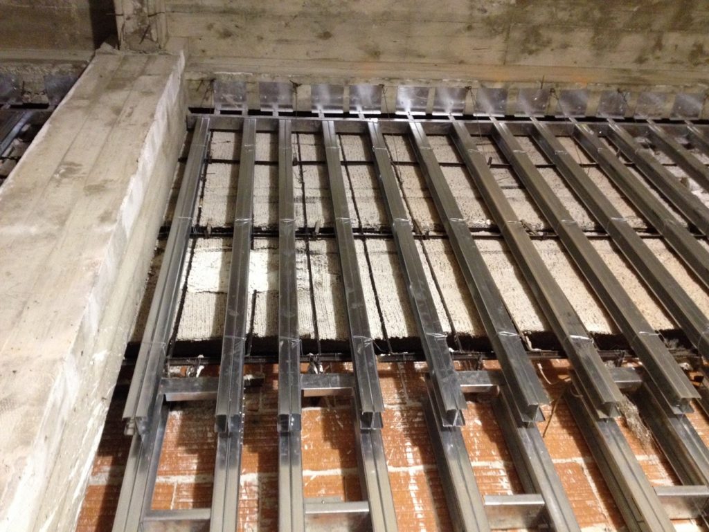
- Installing new steel or wood drag struts to help transfer seismic forces from the wall panels into the roof diaphragm effectively. It is generally not acceptable to rely on 2 inch-wide roof framing members to transfer wall anchor forces into the roof diaphragm.
Example of strut members with 4x wood framing.
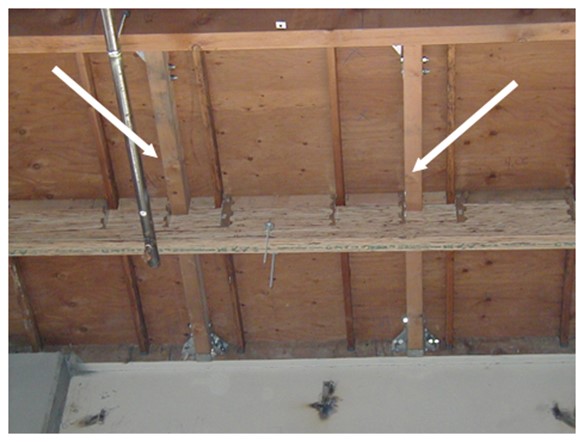
- Adding continuity tie hardware (like wall anchor hardware) to transfer wall anchor forces between the ends of two adjacent and aligned roof framing members to achieve force transfer further into the diaphragm.
Example of continuity ties.
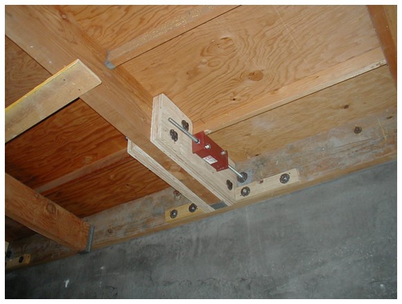
- Supplementing existing collectors and collector connection hardware. Collectors are roof framing members that align with concrete walls and are used to transfer forces into the roof diaphragm at plan irregularities. Connections are required between the concrete shear wall and the collector and between aligned roof framing members across the width of the building.
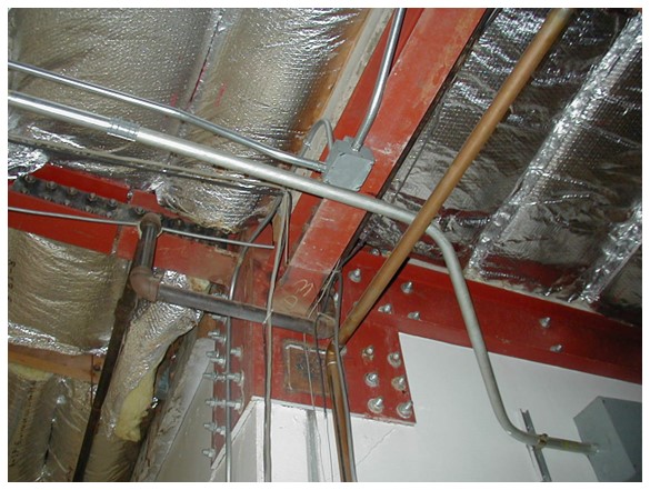
Example of collector connection at re-entrant corner of a tilt-up building.
- Bracing mezzanines that do not have sufficient lateral load systems to avoid damaging the wall panels they are attached to or adjacent to. In some cases, retrofitting or adding a wall anchor system to the mezzanine is required.
Additional considerations for RWFD buildings
Additional retrofits may include:
- Strengthening of roof diaphragms to improve the overall building performance. This typically involves adding nailing from the plywood to the roof framing members below and is normally limited to a small portion of the entire roof. In extreme cases, it can involve adding a second layer of plywood below the framing at locations where additional strength is needed (near concrete walls). To be cost-effective, this strengthening is best achieved in combination with a reroofing project, as roofing must be removed to add nailing. It may be appropriate to complete the rest of the retrofit, but wait until reroofing is scheduled to re-nail the diaphragm. Tilt-up retrofits are usually relatively economical compared to retrofits of other structures, but adding the cost of a new roof can double the cost.
- Walls must have sufficient strength in-plane to transfer earthquake forces to the foundation. Buildings with substantial solid walls typically do not have a need for strengthening. However, a wall elevation with many truck door openings or windows with narrow piers and relatively few solid portions may be deficient for in-plane loads, and strengthening can be considered. This could be achieved by infilling openings with concrete or by thickening some walls by adding shotcrete on the inside. In some cases, tilt-up wall retrofit could include tying adjacent wall panels together. Alternatively, interior walls or braces (with new foundations) could be added to reduce the roof diaphragm span and thus reduce load to the deficient wall.
- Walls must also be able to span out-of-plane between the roof and foundation. Retrofitting walls with insufficient ability to span between the roof and the foundation can be done by adding vertical strong backs (or, in cases where pilasters exist, horizontal strong backs to reduce the wall span), but this may result in the need for foundation work. Alternatively, the walls can be strengthened by using FRP strips on both sides of the wall to improve the flexural capacity. It is likely this can be limited to the middle portion of the wall where the bending forces are highest.
Some RWFD buildings have had significant openings introduced into walls (i.e., a truck door opening). It is important that these added openings were engineered considering earthquakes. Generally, engineered openings will have steel framing added at their edges to provide the flexural reinforcement that is usually provided around designed openings with extra rebar. Without this flexural reinforcement, either out-of-plane or in-plane failure of the wall is possible in an earthquake. Retrofitting openings with steel framing may make such openings acceptable, but it may also be necessary to structurally infill the openings or provide compensating strength elsewhere.