Bridge Inspection Requirements for Fracture-Critical Cable Components

The American Society for Civil Engineers (ASCE) gave the nation’s bridges a C (mediocre) grade in its 2021 Report Card for America’s Infrastructure,1 noting the age and structural deficiency of the current bridge inventory, and calling for a 58% annual increase in bridge rehabilitation spending.
Because cables in cable-supported (CS) bridges have unique details, their inspection requires various non-destructive testing (NDT) technologies and, sometimes, familiarity with advanced structural dynamics. Therefore, the rehabilitation programs for these bridges usually involve multidisciplinary teams to evaluate the existing condition and design appropriate repairs for critical components. This article aims to give an overview of the leading causes of bridge cable deterioration and outline the related inspection requirements and procedures.
How Do Cable Systems Deteriorate?
There are several common causes for cable system deterioration in bridges:
- Corrosion: Adverse environmental conditions such as humidity and moisture inside the cables can cause cable wires to corrode, crack, or break. There are several ways water can penetrate the cables, such as a breakdown in the exterior protection system caused by poorly wrapped cables or cracks in the paint. Other environmental parameters can also cause corrosion, including acid rain, carbonation and bicarbonation, nitration, alkaline environments, seawater and salt spray, and cathodic actions caused by nobler metals coming in contact with steel.
- Fatigue: Fatigue refers to localized damage caused by cyclic stresses of nominal magnitudes well below the static strength of the cable materials. Rain-wind and traffic-induced vibrations in cable stays are two common sources of immature fatigue failures in improperly designed cable systems, although other sources of deterioration such as corrosion and damage due to overloading could further exacerbate the cable’s fatigue performance.
- Extreme Events: Several extreme or unusual events could affect the performance of stay cables, including earthquakes, fires, blasts, impacts, and ice build-up. The cables must be carefully evaluated if they are subjected to these extreme hazards.
What Components of Bridge Cable Systems Require Inspection?
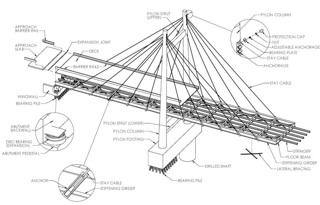
The following components must be part of the inspection programs for cable-stayed bridges:
- Stay Cables: Inspected for cracks or vehicular impact damage on the protective coverings and their retention of design tension forces.
- Pylon and Deck Anchorages: Inspected for water tightness, drainage, and corrosion protection.
- Pylon and Tower Components: Inspected for signs of deterioration or damage.
- Damping Systems: Inspected for overall soundness and effectiveness.
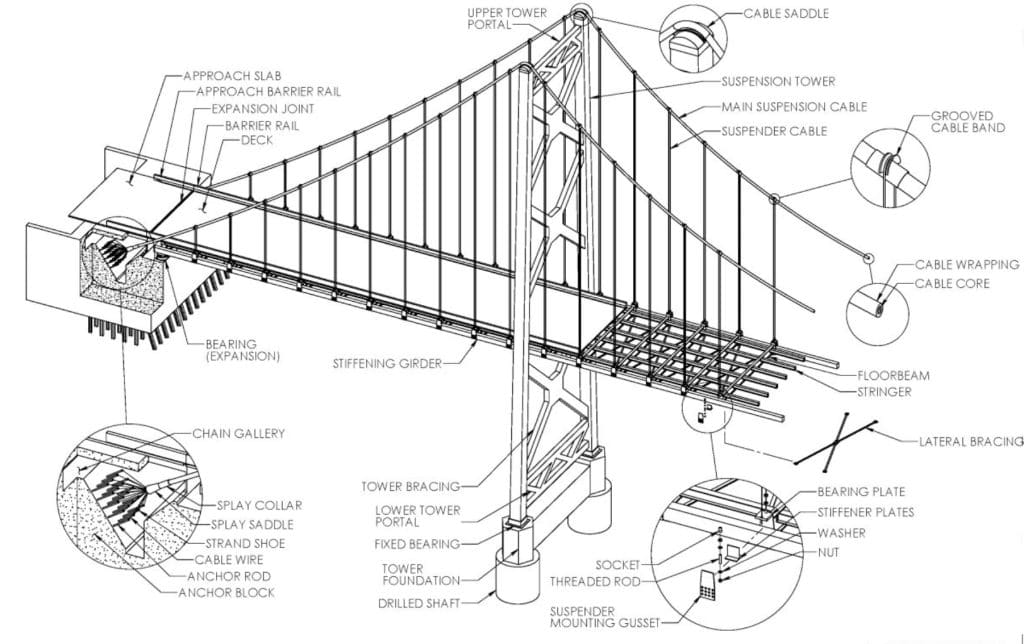
Similarly, the following components must be part of the inspection programs for suspension bridges:
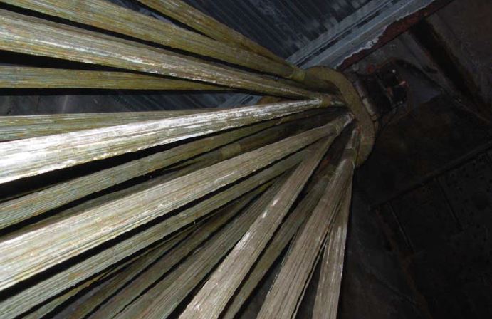
- Main Suspension Cable: Inspected for indications of corroded wires on the main suspension cables, especially at low points of cables, areas adjacent to the cable bands, and saddles over towers.
- Tower and Cable Saddles: Inspected for missing or loose bolts, damaged sleeves, bellows or flashing, and corrosion or cracks in the casting.
- Cable Bands: Inspected for missing or loose bolts, rust stains or dripping water indicative of internal corrosion, or broken suspender saddles.
- Suspender Cables and Connections: Inspected for corrosion or deterioration, broken wires, kinks, or slack, and for their retention of design tension forces.
- Sockets: Inspected for corrosion, cracks, deterioration, and possible movement or abrasion at their connection to the bridge superstructure.
- Anchorages: Inspected for corrosion at all anchorage areas, including the splay saddle, bridge wires, strand shoes or sockets, anchor bars, and chain gallery.
-
- Suspension bridge
-
- Cable-stayed bridge
Bridge components; images courtesy of Iowa Department of Transportation Bridge Inspection Manual3

The insights gained from these assessments will help bridge designers, owners, and maintenance authorities understand the root cause of their bridge deterioration, increase their preparedness for maintaining these structures, and make better-informed decisions to minimize the bridge underperformance risk and future maintenance costs.
What Are the Inspection Requirements for Bridge Cable Components?
The cable members and their corresponding elements are generally categorized as fracture-critical members (FCMs). An FCM is defined as a steel member in tension whose failure could cause part or all of the bridge to collapse. Therefore, maintaining a routine inspection schedule is critical for these members. The current National Bridge Inspection Standards (NBIS) guidance2 requires safety inspections for FCMs in public highway bridges at least once every 24 months although future NBIS revisions are planned to specify the inspection periods based on the bridge performance risk.
Because of the complexities involved in cable system inspections, bridge inspectors need to use various tools and techniques to assess cable conditions, including:
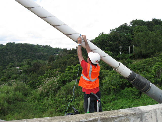
Visual Inspection: This method involves inspecting visible parts for signs of metal corrosion or aging of sealing materials, opening anchor covers and outer sheaths on the main run of the stay cable, opening deviators and dampers, and inspecting internal mechanisms. Some anchor parts may be visually inspected by fiber-optic inspection tools such as borescopes. Inspectors can also visually see the signs of fatigue on the cables via broken wires, cracked covers, etc. However, it is usually difficult to evaluate the fatigue resistance of the anchorage by visual inspection because the structural details of cable anchorages are complex.
Non-Destructive Testing: NDT methods are often required to evaluate the performance of cable elements. Unlike other critical structural components, the cable strands responsible for carrying the structural tension loads are entirely hidden from view by protective cable covers like HDPE pipes. On top of this, the strands are often grouted to provide a corrosion-protection system and are difficult to access. These issues are amplified at the cable anchorage zones and high-stress areas where corrosion barriers are typically discontinuous. Many bridges have also had problems with leakage and moisture accumulation in the lower parts of the anchorages, which NDT methods can detect.
Detecting the effects of corrosion and fatigue in the anchor zones is typically performed by ultrasound testing. Other common NDT methods used for cable inspection include ground-penetrating radar, infrared thermography, and impact echo testing. These NDT methods often lack the resolution required to detect broken wires along cables. Therefore, if there are reasons to believe that there are broken wires (e.g., poor tension force measured in the cables), more sophisticated methods can be used to detect the extent of wire breaks, including magnetic particle testing and X-ray testing.
Tension Force Measurement: Force changes among cables can reveal cable condition deviations attributable to construction activities, deterioration, foundation settlement, accidental impacts, and superstructure modifications. Today, vibration-based methods that utilize advanced structural dynamics are often used to determine tension forces in cables. These methods typically involve measuring the vibration frequencies of the cables and relating those frequencies to tension through mathematical relationships. Using an accelerometer attached to the cable, or a contactless laser vibrometer, ambient cable vibrations created by wind or traffic can be measured, and the cable’s frequency spectra can be analyzed.
Many inspectors use the “taut string” theory to relate vibration frequencies to cable tension. But in many cases, the use of the taut string theory leads to oversimplification and increased errors in force predictions. Some examples in which the taut string theory does not produce accurate results include high sags, short lengths, and high bending stiffness in suspending members. For such cases, more advanced iterative numerical solutions are available to account for complex interactions of parameters such as cable mass, length, sag, bending stiffness, external damping characteristics, and other factors. These solutions enable a much more accurate estimation of cable tension forces, which is very important to avoid any incorrect conclusions about the safety margins of these cables.
Effective Damping Measurement: Damping is the primary mechanism to dissipate excessive rain-wind and traffic-induced vibrations in cable stays and prevent premature fatigue degradation. If the intrinsic damping of the cables is inadequate, external dampers are designed and attached to the cable ends to provide additional damping and reduce their vibrations below acceptable limits. The performance of external dampers may diminish over time due to environmental effects. Therefore, to ensure the cables maintain their minimum required design damping, the effective damping of each cable must be measured as part of the periodic bridge inspection.
Similar to the cable force measurement techniques, the damping measurement involves recording cable vibration accelerations by an accelerometer or contactless laser vibrometer and analyzing the recorded data to calculate the cable’s effective damping. Stochastic or deterministic vibration-based methods such as random vibration theory and exponential decay are often used to measure the cable’s effective damping.
Conclusion
Due to bridge cable supports’ complexity and unique details, a bridge inspection team benefits from engaging specialized experts to complement an overall inspection program. These experts should have in-depth knowledge of the basis for the required NBIS inspection procedures, the effects of in-service degradation on structural performance, nondestructive testing, and advanced structural dynamics. The insights gained from these assessments will help bridge designers, owners, and maintenance authorities understand the root cause of their bridge deterioration, increase their preparedness for maintaining these structures, and make better-informed decisions to minimize the bridge underperformance risk and future maintenance costs.
References
- American Society of Civil Engineers: 2021 Report Card for Americas Infrastructure, Bridges, https://infrastructurereportcard.org/cat-item/bridges/.
- Federal Highway Administration, Bridge Inspector’s Reference Manual, Publication No. FHWA NHI 12-049, December 2012.
- Iowa Department of Transportation, Bridge Inspection Manual, Issued January 1, 2015.
For more information
 Contact Brian Pailes.